20 - 安装座
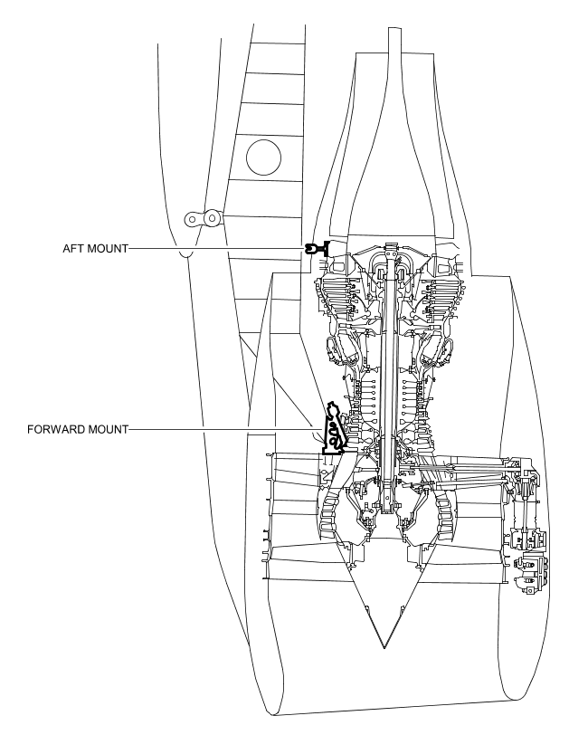
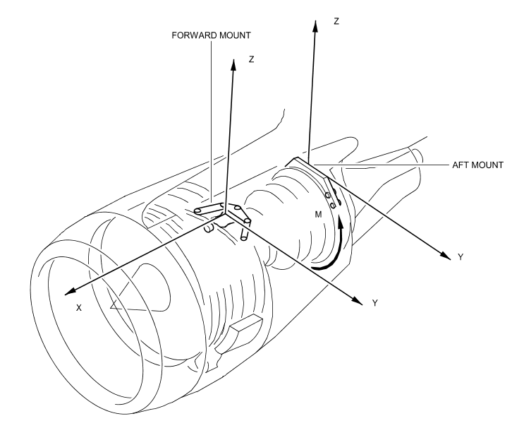
- General (Ref. Fig. Mounts SHEET 1) The engine/pylon connection is achieved by means of a two-mount system : · The forward mount is a damage-tolerant design consisting of a two-piece beam, single piece cross beam, and two links which attach to the pylon and aft fan case. Attached to the beam are two links which are attached to the engine attach brackets. These brackets attach to the engine fan case. · The aft mount is a damage-tolerant design consisting of a two-piece cross beam, that attaches to the pylon. From this beam, there are three, three-piece links which attach to the engine rear frame . 2. System Description (Ref. Fig. Engine Mount Loads SHEET 1) The engine mounts are designed for side, vertical, thrust and torque loads. The damage-tolerant assemblies consist of links and beams with swaged-in spherical bearings on the ends. The link and beam assemblies are bolted to the engine at the engine fan case and turbine rear frame mount, and interface with the pylon. Additional locking and retaining features are provided on the bolts, or pins, at structural attachment points. The engine mount design provides dual load paths to ensure safe operation should one member fail.
21-前座
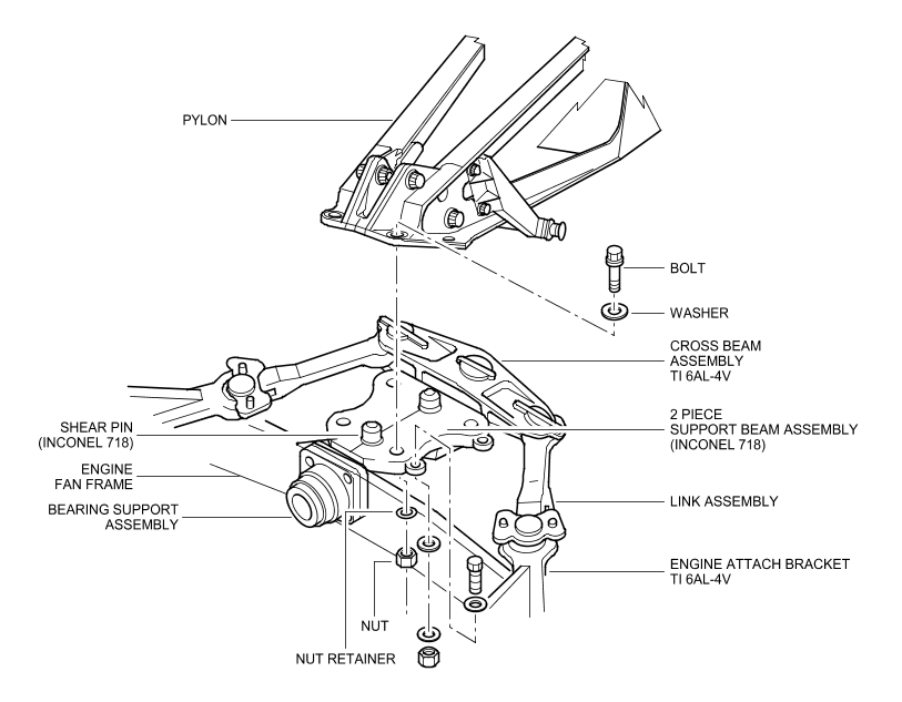
- Description (Ref. Fig. Forward Engine Mount SHEET 1) The forward mount connects the engine aft fan case with the engine pylon forward structure. The forward mount is a damage tolerant design. It consists of : · the support beam assembly : for pylon connection via 4 tension bolts and 2 alignment pins. This fail-safe designed fitting is an assembly of 3 components : 2 half-fittings and 1 plate. · one bearing fitted on the support beam assembly which carries y and z loads. The outer cage is axially free in the engine aft fan frame aperture and therefore carries no x loads. In case of lateral link failure, the bearing partially carries the x loads. · one link/beam/bracket assembly which carries the x thrust loads. The beam is hinged to the main bracket at its center. A link is installed at each end of the beam. A bracket attached to the engine casing supports the front of the link. The link ends have bearings. 2. Material The forward engine mount beam is machined from an Inconel 718 forging. The crossbeam, links and engine attach brackets are machined from 6-4 Titanium.
22-后座
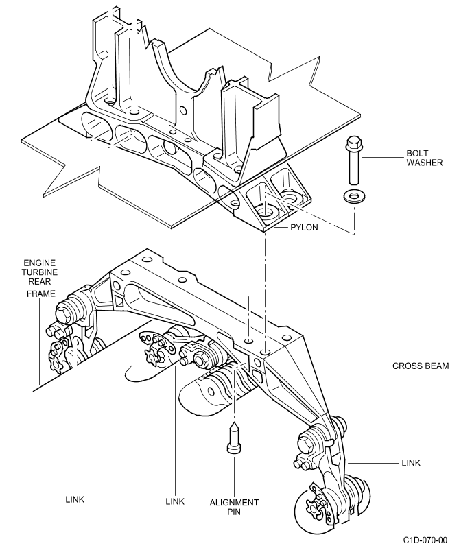
- Description (Ref. Fig. Aft Engine Mount SHEET 1) The aft mount connects the engine turbine rear frame with the engine pylon via a beam. The aft mount takes the loads in the plane normal to the engine centerline, i.e. y, z loads and Mx. The aft mount is a damage tolerant design. It consists of 3 links and a crossbeam assembly. There is a possibility of axial translation movement between the engine casing and the pylon since : · the three links are located in the same plane normal to the engine centerline · the link end have bearings. There is a possibility of axial translation movement between the engine casing and the pylon. This allows for casing expansions of about 0.236 in. (6 mm) in cruise and 0.295 in. (7.5 mm) at maximum thrust. The lugs are located on the upper part of the turbine rear frame. Their angular position is plus or minus 56.25 degrees for the lateral lugs and 11.25 degrees for the upper lug. The aft mount consists of : · 3 fail-safe links. Each link is a triple element stacked assembly. These elements are connected by two attachments. The lower attachment of each link has a bearing. It provides attachment to the engine casing lugs : · a cross beam fitting. The cross beam has 3 lugs for attachment of the 3 links. Each lug includes a bearing. The cross beam has a mating face for connection with the engine pylon. This attachment is made through 4 tension bolts and 2 shear pins. One of the two shear pins is a back-up pin also used as an alignment pin. The cross beam fitting is a fail-safe design : it consists of two lateral parts linked by shear pins. 2. Material The aft mount beam is machined from an Inconel 718 forging. The three links are machined from Inconel 718. 1. Description (Ref. Fig. Aft Engine Mount SHEET 1) The aft mount connects the engine turbine rear frame with the engine pylon via a beam. The aft mount takes the loads in the plane normal to the engine centerline, i.e. y, z loads and Mx. The aft mount is a damage tolerant design. It consists of 3 links and a crossbeam assembly. There is a possibility of axial translation movement between the engine casing and the pylon since : · the three links are located in the same plane normal to the engine centerline · the link end have bearings. There is a possibility of axial translation movement between the engine casing and the pylon. This allows for casing expansions of about 0.236 in. (6 mm) in cruise and 0.295 in. (7.5 mm) at maximum thrust. The lugs are located on the upper part of the turbine rear frame. Their angular position is plus or minus 56.25 degrees for the lateral lugs and 11.25 degrees for the upper lug. The aft mount consists of : · 3 fail-safe links. Each link is a triple element stacked assembly. These elements are connected by two attachments. The lower attachment of each link has a bearing. It provides attachment to the engine casing lugs : · a cross beam fitting. The cross beam has 3 lugs for attachment of the 3 links. Each lug includes a bearing. The cross beam has a mating face for connection with the engine pylon. This attachment is made through 4 tension bolts and 2 shear pins. One of the two shear pins is a back-up pin also used as an alignment pin. The cross beam fitting is a fail-safe design : it consists of two lateral parts linked by shear pins. 2. Material The aft mount beam is machined from an Inconel 718 forging. The three links are machined from Inconel 718.