10 - 整流罩
整流罩把发动机的外缘包起来,因此而形成了发动机短舱。
短舱用于:
- 保护发动机及其附件
- airflow around the engine during its operation.
- 雷击保护
- HIRF and EMI attenuation
NOTE
Fan cowls and thrust reversers are not removed for an engine change.

11-进气整流罩
General
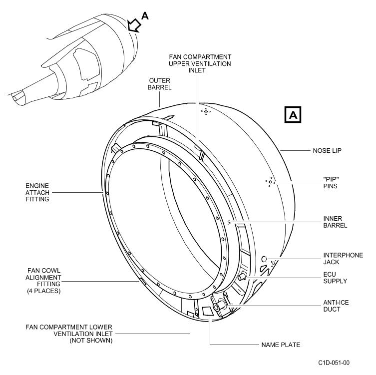
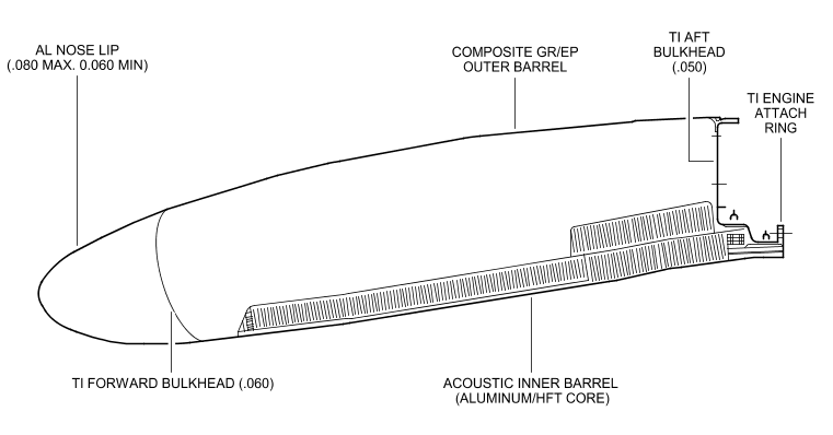
The engine air intake cowl structure is an interchangeable aerodynamically faired assembly.
It is mounted to the forward face of the engine fan case A1 flange.
The assembly is composed of :
- an inner and outer barrel
- a nose lip
- a forward and an aft bulkhead.
The assembly also includes installation of :
- the anti-icing ducting
- the engine control unit cooling inlet and exhaust
- the interphone/ground jack
- the T2 sensor
- hoisting provisions
- pip pin receptacles for the intake cover.
Description
Air Intake Cowl Configuration
The outer barrel of the air intake cowl is made of two panels of composite construction and an aluminium access panel.
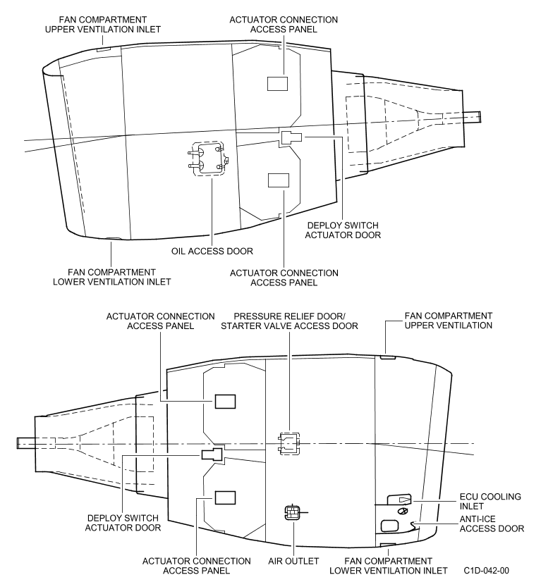
The outer barrel assembly features include a pressure relief door to protect the inlet cowl structure against a burst of the anti-ice supply line.
This pressure relief door is located on the access panel which includes the anti-ice air exhaust duct.
The outer barrel assembly also includes an inlet scoop which provides cooling air to the Engine Control Unit (ECU) and two inlet scoops which provide air for ventilating the fan compartment.
All of these inlet scoops are located on the outer barrel and penetrate the inlet cowl aft bulkhead which forms the forward part of fan compartment fire barrier.
Other features on the outer barrel assembly include a phone jack, hoisting provisions, and pip pins for the inlet cowl cover, and fan cowl door alignment fittings.
The fan cowl alignment fittings are controlled on the inlet cowl aft bulkhead outer ring and align/position the fan cowl doors to ensure proper gaps are maintained between the inlet cowl, fan cowl, and thrust reverser.
The composite skin of the inlet cowl outer barrel incorporates a lightning protection system consisting of an expanded copper screen (ECS) material.
This material enables the inlet cowl to satisfy Zone 1A lightening strike requirements.
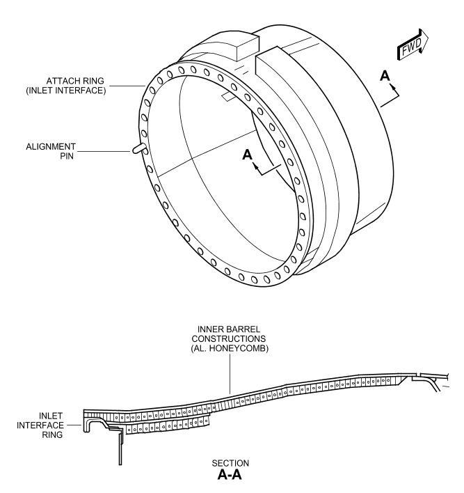
The inner barrel consists of three acoustically treated structural bonded panels, which are assembled with mechanical fasteners, and attached to an engine attach ring.
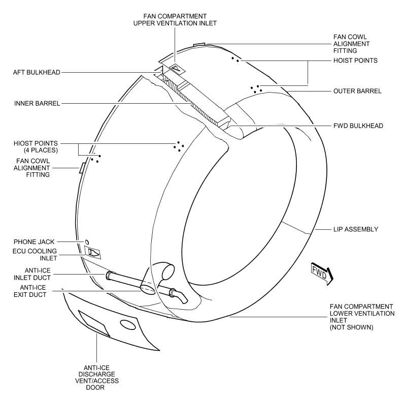
The aft bulkhead and nose lip assembly are connected to the outer barrel and the inner barrel.
Air Intake Cowl Anti-Icing
The nose lip assembly consists of an outer lip skin and bulkhead.
The lip skin and bulkhead comprise the anti-icing "D" duct.
A swirl nozzle is mounted in the "D" duct for distribution of the anti-icing air into the "D" duct.
A supply tube supplies the anti-icing air to the swirl nozzle.
The supply tube penetrates the "D" duct bulkhead.
A slip joint is provided at the "D" duct bulkhead to allow for duct thermal expansion.
Engine bleed air comes into the nose lip cavity through the swirl nozzle.
The air exits into the air intake cowl cavity aft of the "D" duct bulkhead : the air passes through openings in the "D" duct bulkhead inner cap.
The air exhausts overboard through a flush exit duct in the outer barrel.
A deflector is provided at the "D" duct exit.
It prevents direct anti-icing air impingement on the forward portion of the acoustic inner barrel panels.
The system is capable of operation under all ground and flight conditions.
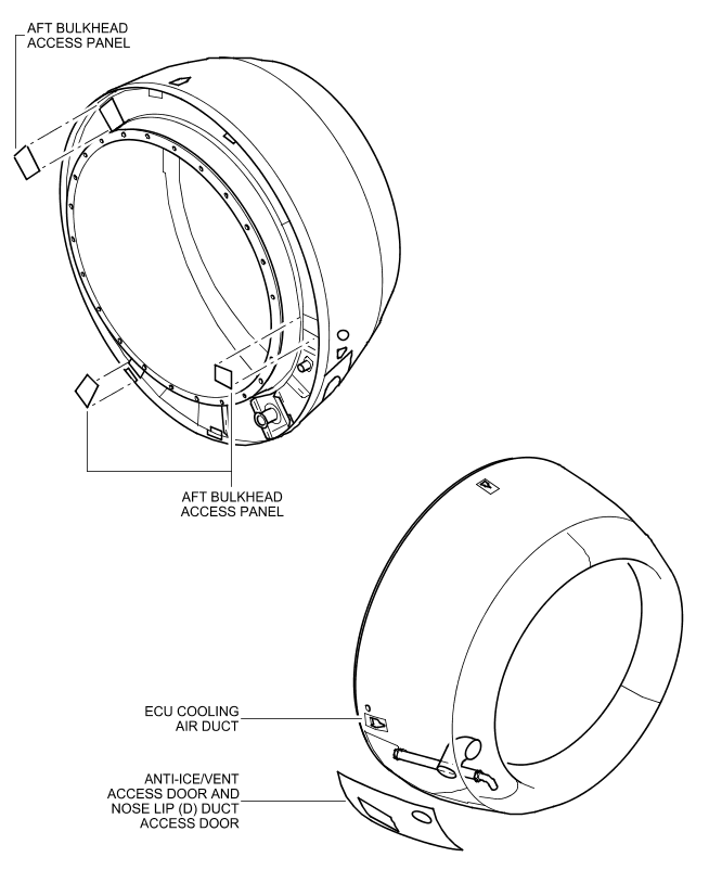
Air Intake Cowl Access
There are a total of five access and inspection locations in the air intake cowl.
Three inspection panels are located on the aft bulkhead.
The access panel is located on the outer barrel and contains the anti-ice exhaust exit and pressure relief door.
The fifth access location is on the forward bulkhead.
This panel provides access to the anti-ice supply duct.
The swirl nozzle is accessible after removing the dedicated anti-ice exhaust duct.
Air Intake Cowl Acoustic Treatment
The inner barrel is a bonded aluminum honeycomb structure.
Air Intake Cowl Structure
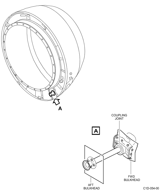
The majority of the internal pressure loads and external air loads are taken in hoop tension through the inner barrel skins.
Longitudinal and transverse loads due to the inlet cowl structure's own inertia as well as any internal or external loads not taken in hoop tension, are distributed into the fan case forward flange through a bolted joint.
Thirty-six identical attachment bolts and one alignment pin are provided.
Special spacers intalled with each attachment bolt help in absorbing engine blade out loads.
The acoustic panels are structural and, as such, carry air intake cowl loads.
The intake cowl aft bulkhead forms a land for the fan cowl leading edge.
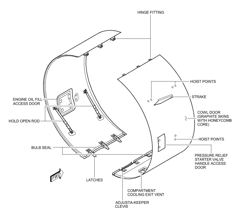
13-风扇整流罩
General
ON A/C 001-050
The fan cowl door assemblies are interchangeable units.
They enclose the engine fan case between the air intake cowl and thrust reverser.
Each fan cowl door assembly incorporates strakes.
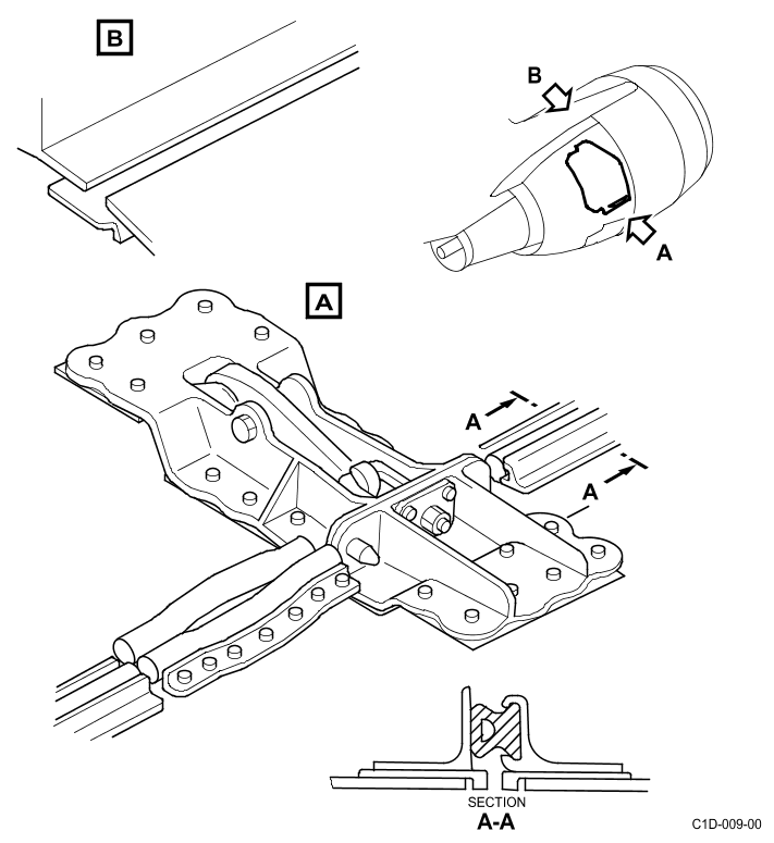
Each assembly is supported by three hinges at the pylon and latched along the bottom centerline with three adjustable tension hook latches.
ON A/C 101-150
The fan cowl door assemblies are interchangeable units.
They enclose the engine fan case between the air intake cowl and thrust reverser.
Inboard fan cowl door of each nacelle incorporates strakes.
Each assembly is supported by three hinges at the pylon and latched along the bottom centerline with three adjustable tension hook latches.
ON A/C ALL
Description
ON A/C 001-050
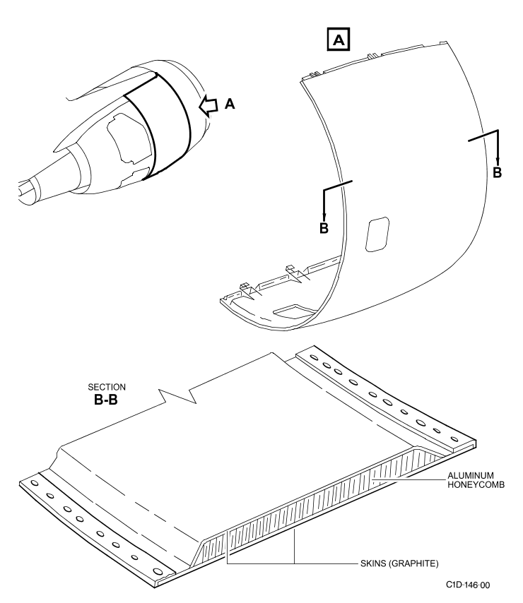
The fan cowls are bonded graphite epoxy skins and aluminum honeycomb sandwich construction.
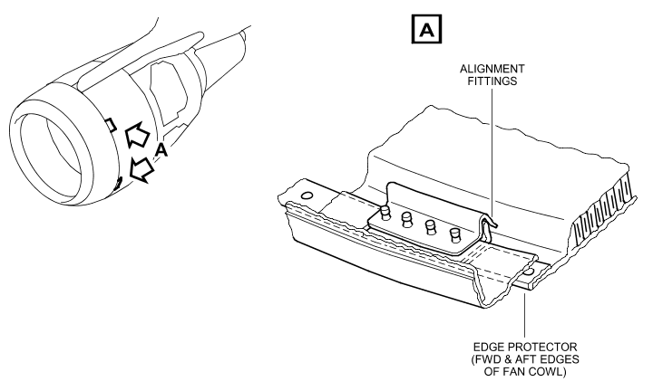
A land is effected with the air intake cowl at the forward end, and with the fan thrust reverser at the aft end. Both lands incorporate an edge protector.
The forward land incorporates two fan cowl locator fittings (associated with air intake cowl alignment fitting).
A composite outer skin of the fan cowl incorporates a lightning protection system consisting of an expanded copper screen (ECS) material.
This material enables the fan cowl to satisfy Zone 1A lightning strike requirements.
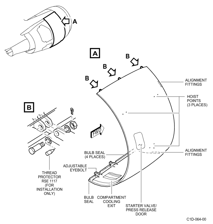
A bulb-type seal is provided along the lower longitudinal splitline and a sheet metal rub strip is provided along the upper longitudinal splitline which interfaces with a pylon mounted sheet metal seal.
Strakes are installed on the right and the left side of the fan cowl doors of each engine.
An electrical bonding strip, which is connected to the strake backplate and the fan cowl locator blade provides an electrical bond between the strake and the engine.
ON A/C 101-150
The fan cowls are bonded graphite epoxy skins and aluminum honeycomb sandwich construction.
A land is effected with the air intake cowl at the forward end, and with the fan thrust reverser at the aft end.
Both lands incorporate an edge protector.
The forward land incorporates two fan cowl locator fittings (associated with air intake cowl alignment fitting).
A composite outer skin of the fan cowl incorporates a lightning protection system consisting of an expanded copper screen (ECS) material.
This material enables the fan cowl to satisfy Zone 1A lightning strike requirements.
A bulb-type seal is provided along the lower longitudinal splitline and a sheet metal rub strip is provided along the upper longitudinal splitline which interfaces with a pylon mounted sheet metal seal.
Strakes are installed on the inboard fan cowl door of each engine.
An electrical bonding strip, which is connected to the strake backplate and the fan cowl locator blade provides an electrical bond between the strake and the engine.
ON A/C ALL
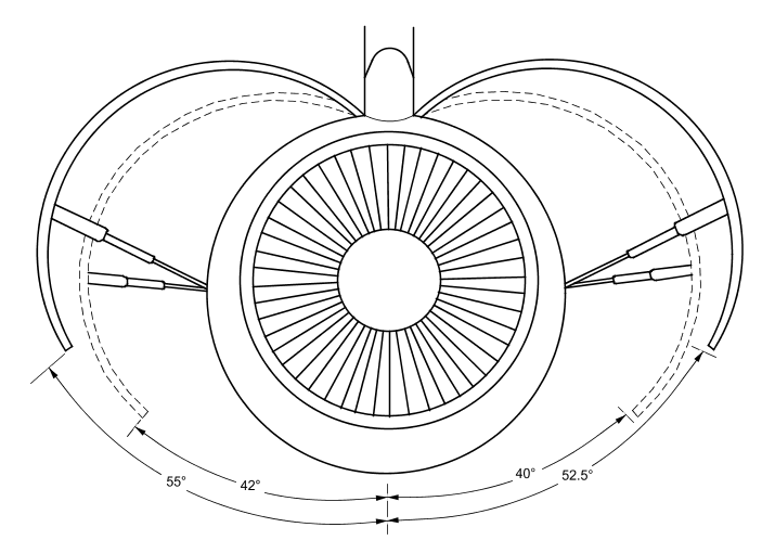
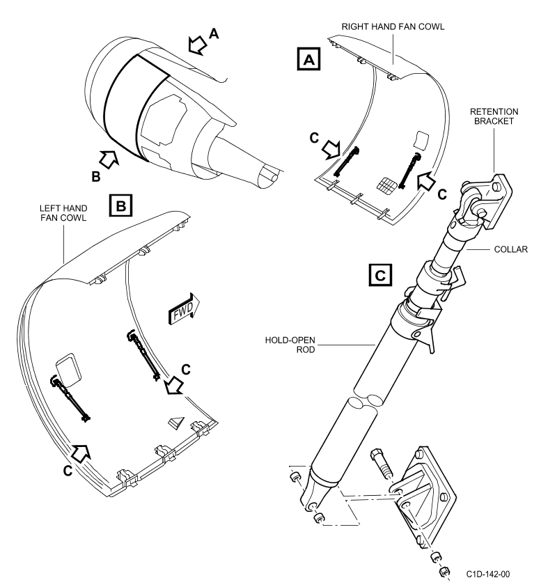
Opening/Closing
There are two telescopic hold open rods on each door.
The hold open rods lock to brackets on the engine fan case.
They support the fan cowl doors in the open position.
A 40-degree position serves for routine maintenance and a 55-degree position serves for increased access.
Three hook type latches are provided on the left hand door, and mating adjusta-keeper clevis on the right hand door.
The bottom seal pressure between the doors is adjustable by varying the shim pack thickness behind the latch striker pads.
The latch handle closing pressure is adjustable with the fan cowl doors closed.
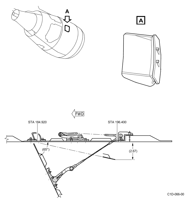
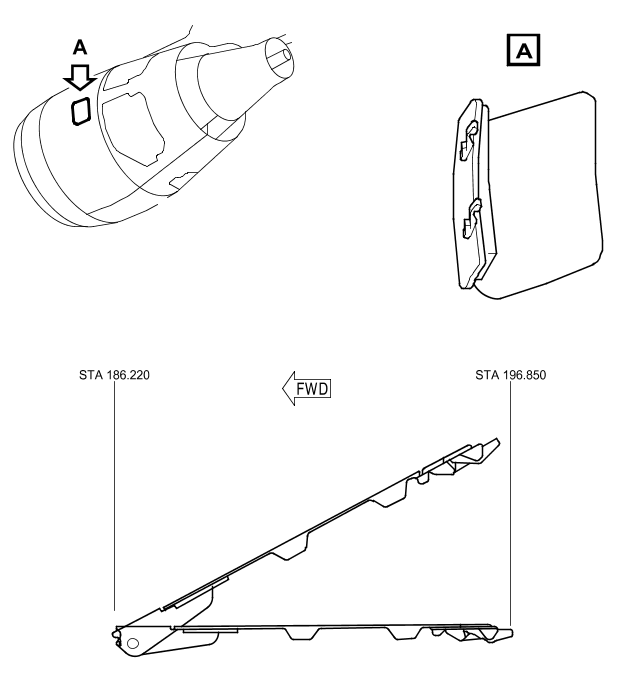
Access Doors/Pressure Relief Door
A combination access/pressure relief door is provided in the right-hand fan cowl door for access to the starter valve manual override.
This door also acts as a pressure relief door to protect the door structure in the event of a burst duct.
The left-hand fan cowl door includes an access door for engine oil servicing and inspection of the hydraulic case drain filter clogging indicator and master oil chip detector indicator.
The air outlet vent is located in the right-hand cowl panel lower aft section.
The fan cowl doors are fireproof without external air flow above the 45-degree radial and fireproof with external air flow below the 45-degree radial.
In addition, the doors are fire resistant without external air flow below the 45-degree radial.
Fan Cowl Structure
The internal pressure loads and external air loads are reacted through the honeycomb structure.
They are transmitted into the pylon through the hinge fittings.
The door lands provide support to prevent deflection under pressure.
The cowl doors, when completely latched, provide hoop continuity.
The cowl doors are designed to be structurally adequate when any one latch is unlatched or any one hinge failed.
A nacelle overpressurization condition due to a pneumatic duct failure is released through the pressure relief door.
The pressure relief doors are designed to prevent fan compartment pressure from exceeding 4 psid (0.28 bar).