00 概述
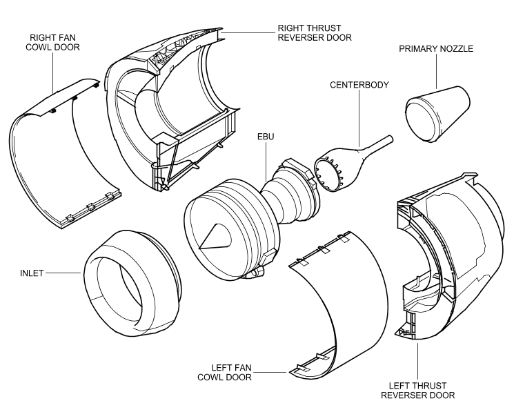
- General (Ref. Fig. Nacelle SHEET 1) Each engine is housed in a nacelle suspended from a pylon attached to the wing lower surface. The nacelle is defined as being the set of cowling and system hardware which, fitted on the engine, constitutes a complete flightworthy propulsion system, ready for installation on the airplane. The nacelle consists of the demountable powerplant, the fan cowls, and the thrust reverser cowls. The demountable powerplant consists of the engine and its accessories, the engine air intake, the primary exhaust (including centerbody) and the engine mounts. The Engine Build Up (EBU) consists of the engine and its accessories without the engine air intake, the primary exhaust (including centerbody). The Quick Engine Change (QEC) consists of the engine and its accessories and additional items dependent on selected configuration. The propulsion systems mounted on the right and left wings are interchangeable except for the fan cowl door strake. Each fan cowl incorporates provisions for mounting the strake; the strake is to be installed on the inboard and outboard side of each propulsion system. 2. Description A. Engine (Ref. AMM D/O 72-00-00-00) (Ref. Fig. Engine - Schematic SHEET 1) The engine is a dual-rotor, variable stator, high-bypass ratio turbofan power plant for subsonic service. The design and configuration of the engine are based on obtaining long life high reliability and easy access for line maintenance. It is a modular design which permits the changing of a major assembly without complete dissassembly of the engine. The principal modules of the engine are the low pressure compressor (fan stator and fan rotor), high pressure compressor, turbine frame, combustor chamber, high pressure turbine, low pressure turbine and gearbox. B. Cowling (Ref. AMM D/O 71-10-00-00) (Ref. Fig. Nacelle Dimensions SHEET 1) The cowling assembly consists of : · the air intake cowl · the fan cowl · the thrust reverser cowl · the primary exhaust (primary nozzle and center body). The thrust reverser and the primary exhaust are covered by chapter 78. The hinged thrust reverser and fan cowls are attached to the pylon. The fan cowls are hinged at the upper part by three hinges. They are held open by hold-open rods and provide access to the engine for : · maintenance · rigging · trouble shooting · engine removal/installation C. Mounts (Ref. AMM D/O 71-20-00-00) The engine is attached to the pylon by two damage tolerant mounts. The mounts are the main attaching structures (forward and aft). The forward mount comprises four attach bolts that connect the engine directly to the pylon. The aft mount consists of a link and beam system attaching the engine to the pylon. D. Attachment Fittings (Ref. AMM D/O 71-40-00-00) The attachment fittings and support brackets ensure the attachment on the engine of : · components · ducts · pipes · electrical cables The attachment fittings and support brackets are attached on : · the engine core · the fan case · the accessories · the accessory gearbox. E. Fire Protection (Ref. AMM D/O 26-00-00-00) Firewalls and fire seals provide segregation and fire protection between the engine compartments (fan and core compartments). The fire seals separate the space within the engine into compartments. This means of isolation limits propagation, should a fire occur. The pylon floor forms the upper firewall of both the fan and core compartments. F. Electrical Harness (Ref. AMM D/O 71-50-00-00) The engine electrical harness serves for connection with the electrical components mounted in the nacelle pylon. The engine electrical harness : (1) distributes the power required by the aircraft electrical system, (2) transmits signals for : · nacelle sub-systems · engine control · monitoring functions. G. Engine Drains (Ref. AMM D/O 71-70-00-00) The drain and vent system consists of lines collecting and carrying waste fluids and vapors overboard. This system drains accessories and engine components. H. Lightning Protection and Grounding (Ref. Fig. Lightning Zones SHEET 1) The composite outer skins of the inlet cowl and fan cowl incorporate a lightning protection system (Ref. 71-11-00 and 71-13-00). Mechanical attachment and fittings conduct the current into the pylon/engine structure. J. HIRF and EMI The inlet cowl and fan cowl composite graphite outer skins incorporate an Expanded Copper Screen (ECS) which increases the electromagnetic compatibility of the structure. The continuous fan cowl door to pylon rub strip is made of corrosion resistant steel materials which closes the electromagnetic aperture of this joint. The fan compartment ventilation scoops are made of 321 steel material and the fan compartment ventilation exhaust located in the lower right hand fan cowl door features an Inconel 625 grid which screens electromagnetic signals. K. Ventilation (Ref. 75-00-00) The engine fan and core compartments are ventilated to maintain equipment, and fluid, temperatures at suitable levels. Ventilation of the compartments also contributes to fire prevention by eliminating the buildup of flammable fluids, or vapors, to dangerous levels. 1. General (Ref. Fig. Nacelle SHEET 1) Each engine is housed in a nacelle suspended from a pylon attached to the wing lower surface. The nacelle is defined as being the set of cowling and system hardware which, fitted on the engine, constitutes a complete flightworthy propulsion system, ready for installation on the airplane. The nacelle consists of the demountable powerplant, the fan cowls, and the thrust reverser cowls. The demountable powerplant consists of the engine and its accessories, the engine air intake, the primary exhaust (including centerbody) and the engine mounts. The Engine Build Up (EBU) consists of the engine and its accessories without the engine air intake, the primary exhaust (including centerbody). The Quick Engine Change (QEC) consists of the engine and its accessories and additional items dependent on selected configuration. The propulsion systems mounted on the right and left wings are interchangeable except for the fan cowl door strake. Each fan cowl incorporates provisions for mounting the strake; the strake is to be installed on the inboard and outboard side of each propulsion system. 2. Description A. Engine (Ref. AMM D/O 72-00-00-00) (Ref. Fig. Engine - Schematic SHEET 1) The engine is a dual-rotor, variable stator, high-bypass ratio turbofan power plant for subsonic service. The design and configuration of the engine are based on obtaining long life high reliability and easy access for line maintenance. It is a modular design which permits the changing of a major assembly without complete dissassembly of the engine. The principal modules of the engine are the low pressure compressor (fan stator and fan rotor), high pressure compressor, turbine frame, combustor chamber, high pressure turbine, low pressure turbine and gearbox. B. Cowling (Ref. AMM D/O 71-10-00-00) (Ref. Fig. Nacelle Dimensions SHEET 1) The cowling assembly consists of : · the air intake cowl · the fan cowl · the thrust reverser cowl · the primary exhaust (primary nozzle and center body). The thrust reverser and the primary exhaust are covered by chapter 78. The hinged thrust reverser and fan cowls are attached to the pylon. The fan cowls are hinged at the upper part by three hinges. They are held open by hold-open rods and provide access to the engine for : · maintenance · rigging · trouble shooting · engine removal/installation C. Mounts (Ref. AMM D/O 71-20-00-00) The engine is attached to the pylon by two damage tolerant mounts. The mounts are the main attaching structures (forward and aft). The forward mount comprises four attach bolts that connect the engine directly to the pylon. The aft mount consists of a link and beam system attaching the engine to the pylon. D. Attachment Fittings (Ref. AMM D/O 71-40-00-00) The attachment fittings and support brackets ensure the attachment on the engine of : · components · ducts · pipes · electrical cables The attachment fittings and support brackets are attached on : · the engine core · the fan case · the accessories · the accessory gearbox. E. Fire Protection (Ref. AMM D/O 26-00-00-00) Firewalls and fire seals provide segregation and fire protection between the engine compartments (fan and core compartments). The fire seals separate the space within the engine into compartments. This means of isolation limits propagation, should a fire occur. The pylon floor forms the upper firewall of both the fan and core compartments. F. Electrical Harness (Ref. AMM D/O 71-50-00-00) The engine electrical harness serves for connection with the electrical components mounted in the nacelle pylon. The engine electrical harness : (1) distributes the power required by the aircraft electrical system, (2) transmits signals for : · nacelle sub-systems · engine control · monitoring functions. G. Engine Drains (Ref. AMM D/O 71-70-00-00) The drain and vent system consists of lines collecting and carrying waste fluids and vapors overboard. This system drains accessories and engine components. H. Lightning Protection and Grounding (Ref. Fig. Lightning Zones SHEET 1) The composite outer skins of the inlet cowl and fan cowl incorporate a lightning protection system (Ref. 71-11-00 and 71-13-00). Mechanical attachment and fittings conduct the current into the pylon/engine structure. J. HIRF and EMI The inlet cowl and fan cowl composite graphite outer skins incorporate an Expanded Copper Screen (ECS) which increases the electromagnetic compatibility of the structure. The continuous fan cowl door to pylon rub strip is made of corrosion resistant steel materials which closes the electromagnetic aperture of this joint. The fan compartment ventilation scoops are made of 321 steel material and the fan compartment ventilation exhaust located in the lower right hand fan cowl door features an Inconel 625 grid which screens electromagnetic signals. K. Ventilation (Ref. 75-00-00) The engine fan and core compartments are ventilated to maintain equipment, and fluid, temperatures at suitable levels. Ventilation of the compartments also contributes to fire prevention by eliminating the buildup of flammable fluids, or vapors, to dangerous levels. 1. General (Ref. Fig. Nacelle SHEET 1) Each engine is housed in a nacelle suspended from a pylon attached to the wing lower surface. The nacelle is defined as being the set of cowling and system hardware which, fitted on the engine, constitutes a complete flightworthy propulsion system, ready for installation on the airplane. The nacelle consists of the demountable powerplant, the fan cowls, and the thrust reverser cowls. The demountable powerplant consists of the engine and its accessories, the engine air intake, the primary exhaust (including centerbody) and the engine mounts. The Engine Build Up (EBU) consists of the engine and its accessories without the engine air intake, the primary exhaust (including centerbody). The Quick Engine Change (QEC) consists of the engine and its accessories and additional items dependent on selected configuration. The propulsion systems mounted on the right and left wings are interchangeable except for the fan cowl door strake. Each fan cowl incorporates provisions for mounting the strake; the strake is to be installed on the inboard and outboard side of each propulsion system. 2. Description A. Engine (Ref. AMM D/O 72-00-00-00) (Ref. Fig. Engine - Schematic SHEET 1) The engine is a dual-rotor, variable stator, high-bypass ratio turbofan power plant for subsonic service. The design and configuration of the engine are based on obtaining long life high reliability and easy access for line maintenance. It is a modular design which permits the changing of a major assembly without complete dissassembly of the engine. The principal modules of the engine are the low pressure compressor (fan stator and fan rotor), high pressure compressor, turbine frame, combustor chamber, high pressure turbine, low pressure turbine and gearbox. B. Cowling (Ref. AMM D/O 71-10-00-00) (Ref. Fig. Nacelle Dimensions SHEET 1) The cowling assembly consists of : · the air intake cowl · the fan cowl · the thrust reverser cowl · the primary exhaust (primary nozzle and center body). The thrust reverser and the primary exhaust are covered by chapter 78. The hinged thrust reverser and fan cowls are attached to the pylon. The fan cowls are hinged at the upper part by three hinges. They are held open by hold-open rods and provide access to the engine for : · maintenance · rigging · trouble shooting · engine removal/installation C. Mounts (Ref. AMM D/O 71-20-00-00) The engine is attached to the pylon by two damage tolerant mounts. The mounts are the main attaching structures (forward and aft). The forward mount comprises four attach bolts that connect the engine directly to the pylon. The aft mount consists of a link and beam system attaching the engine to the pylon. D. Attachment Fittings (Ref. AMM D/O 71-40-00-00) The attachment fittings and support brackets ensure the attachment on the engine of : · components · ducts · pipes · electrical cables The attachment fittings and support brackets are attached on : · the engine core · the fan case · the accessories · the accessory gearbox. E. Fire Protection (Ref. AMM D/O 26-00-00-00) Firewalls and fire seals provide segregation and fire protection between the engine compartments (fan and core compartments). The fire seals separate the space within the engine into compartments. This means of isolation limits propagation, should a fire occur. The pylon floor forms the upper firewall of both the fan and core compartments. F. Electrical Harness (Ref. AMM D/O 71-50-00-00) The engine electrical harness serves for connection with the electrical components mounted in the nacelle pylon. The engine electrical harness : (1) distributes the power required by the aircraft electrical system, (2) transmits signals for : · nacelle sub-systems · engine control · monitoring functions. G. Engine Drains (Ref. AMM D/O 71-70-00-00) The drain and vent system consists of lines collecting and carrying waste fluids and vapors overboard. This system drains accessories and engine components. H. Lightning Protection and Grounding (Ref. Fig. Lightning Zones SHEET 1) The composite outer skins of the inlet cowl and fan cowl incorporate a lightning protection system (Ref. 71-11-00 and 71-13-00). Mechanical attachment and fittings conduct the current into the pylon/engine structure. J. HIRF and EMI The inlet cowl and fan cowl composite graphite outer skins incorporate an Expanded Copper Screen (ECS) which increases the electromagnetic compatibility of the structure. The continuous fan cowl door to pylon rub strip is made of corrosion resistant steel materials which closes the electromagnetic aperture of this joint. The fan compartment ventilation scoops are made of 321 steel material and the fan compartment ventilation exhaust located in the lower right hand fan cowl door features an Inconel 625 grid which screens electromagnetic signals. K. Ventilation (Ref. 75-00-00) The engine fan and core compartments are ventilated to maintain equipment, and fluid, temperatures at suitable levels. Ventilation of the compartments also contributes to fire prevention by eliminating the buildup of flammable fluids, or vapors, to dangerous levels.
- EBU:发动机总成,由发动机及其附件组成,不含发动机进气口、主喷管、中心体
- QEC:发动机快速更换,由发动机及其附件和一些其他附加设备组成
推力系统挂载在左右大翼上,并且可以互换(除了风扇包皮)。
1、发动机概述(CFM56)
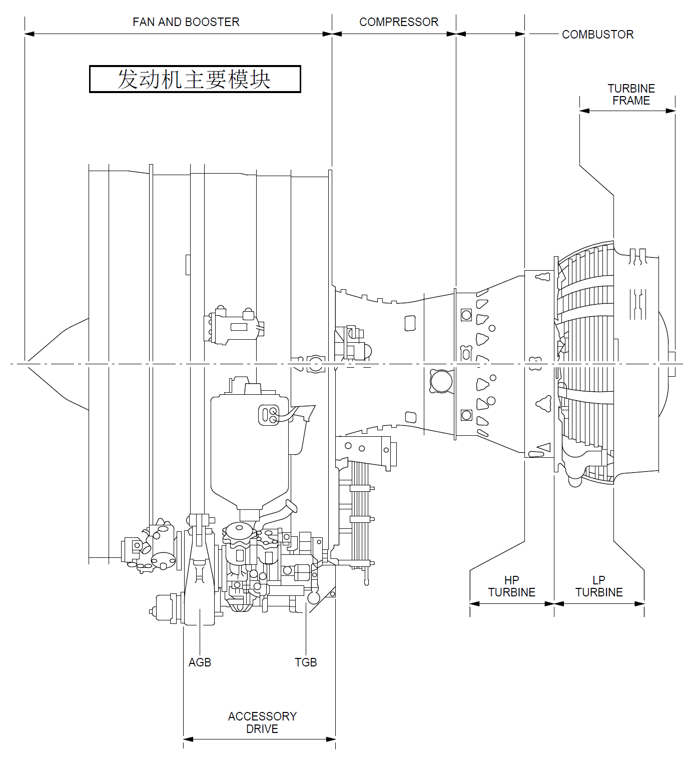
发动机是一个双转子、可调静子、高涵道比涡扇发动机,采用模块化的设计,这样可以不必完全拆解发动机,就可以更换主要的部件,主要模块为:低压压气机(风扇静子和风扇转子)、高压压气机、涡轮机匣、燃烧室、高压涡轮、低压涡轮、齿轮盒。
2、整流罩
整流罩包裹在发动机的外面,因此形成了发动机短舱,短舱有很多作用,例如:
- 保护发动机及其附件
- 防雷击
- 防高强度辐射场和电磁干扰
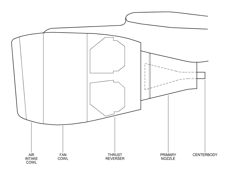
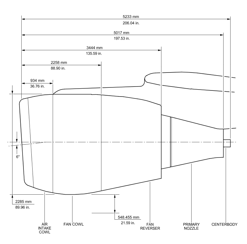
发动机整流罩包括:
- 进气道整流罩
- 风扇整流罩
- 反推整流罩
- 主排气口(含主喷管和中心体)
a. 进气整流罩
FIN号:
1100KM1
1100KM2
进气整流罩整体结构上是一个可互换的气动力学流线型的组件,它装在风扇机匣的A1法兰盘上
进气整流罩的组成:
- 内筒和外筒
- 唇口
- 前后壁板
进气整流罩组件上安装得有:
- 防冰管道
- ECU冷却的进气口和排气口
- 内话/地面耳机的插口
- T2传感器
- 吊点
- "pip"针的插座
a.1 进气整流罩的构造
外筒由两块复合材料结构的板子和一个铝制的盖板组成。
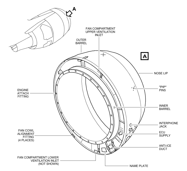
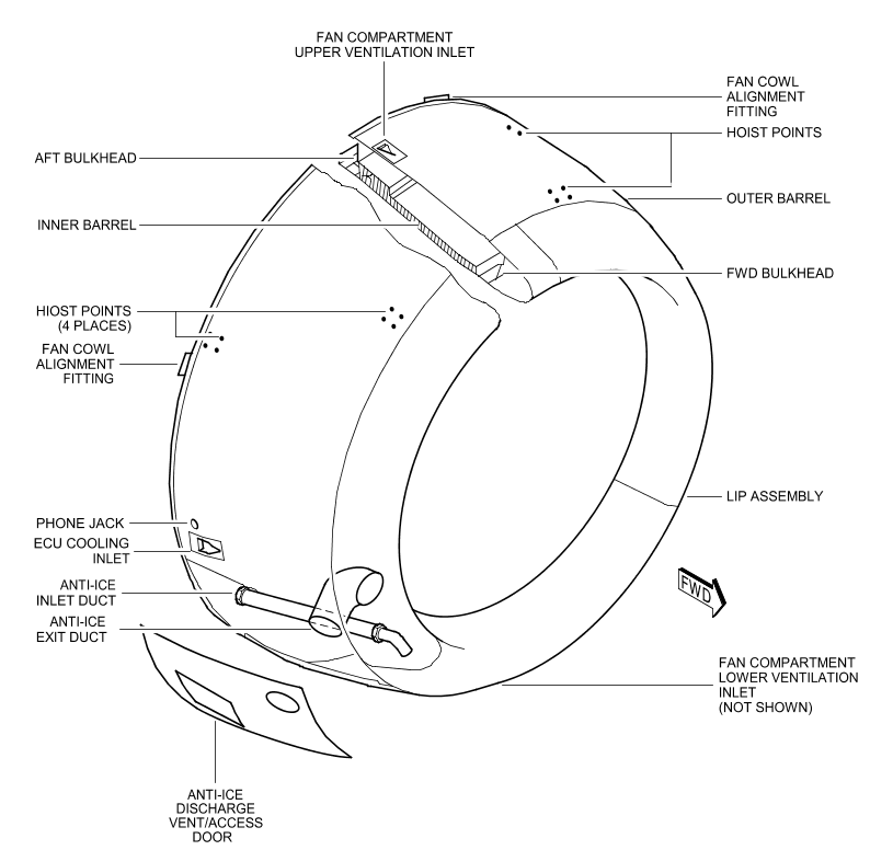
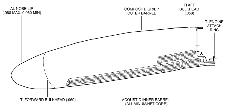 外筒上有一个压力释放门,用于防止进气整流罩防冰管道爆裂。外筒上还有一个进气口,用于给ECU提供冷却空气,还有两个进气口用于给风扇机匣通风。The outer barrel of the air intake cowl is made of two panels of composite construction and an aluminium access panel. The outer barrel assembly features include a pressure relief door to protect the inlet cowl structure against a burst of the anti-ice supply line. This pressure relief door is located on the access panel which includes the anti-ice air exhaust duct. The outer barrel assembly also includes an inlet scoop which provides cooling air to the Engine Control Unit (ECU) and two inlet scoops which provide air for ventilating the fan compartment. All of these inlet scoops are located on the outer barrel and penetrate the inlet cowl aft bulkhead which forms the forward part of fan compartment fire barrier. Other features on the outer barrel assembly include a phone jack, hoisting provisions, and pip pins for the inlet cowl cover, and fan cowl door alignment fittings. The fan cowl alignment fittings are controlled on the inlet cowl aft bulkhead outer ring and align/position the fan cowl doors to ensure proper gaps are maintained between the inlet cowl, fan cowl, and thrust reverser. The composite skin of the inlet cowl outer barrel incorporates a lightning protection system consisting of an expanded copper screen (ECS) material. This material enables the inlet cowl to satisfy Zone 1A lightening strike requirements. The inner barrel consists of three acoustically treated structural bonded panels, which are assembled with mechanical fasteners, and attached to an engine attach ring. The aft bulkhead and nose lip assembly are connected to the outer barrel and the inner barrel.
The majority of the internal pressure loads and external air loads are taken in hoop tension through the inner barrel skins. Longitudinal and transverse loads due to the inlet cowl structure's own inertia as well as any internal or external loads not taken in hoop tension, are distributed into the fan case forward flange through a bolted joint. Thirty-six identical attachment bolts and one alignment pin are provided. Special spacers intalled with each attachment bolt help in absorbing engine blade out loads. The acoustic panels are structural and, as such, carry air intake cowl loads. The intake cowl aft bulkhead forms a land for the fan cowl leading edge.
a.2 进气整流罩防冰
The nose lip assembly consists of an outer lip skin and bulkhead. The lip skin and bulkhead comprise the anti-icing "D" duct. A swirl nozzle is mounted in the "D" duct for distribution of the anti-icing air into the "D" duct. A supply tube supplies the anti-icing air to the swirl nozzle. The supply tube penetrates the "D" duct bulkhead. A slip joint is provided at the "D" duct bulkhead to allow for duct thermal expansion. Engine bleed air comes into the nose lip cavity through the swirl nozzle. The air exits into the air intake cowl cavity aft of the "D" duct bulkhead : the air passes through openings in the "D" duct bulkhead inner cap. The air exhausts overboard through a flush exit duct in the outer barrel. A deflector is provided at the "D" duct exit. It prevents direct anti-icing air impingement on the forward portion of the acoustic inner barrel panels. The system is capable of operation under all ground and flight conditions
a.3 进气整流罩盖板
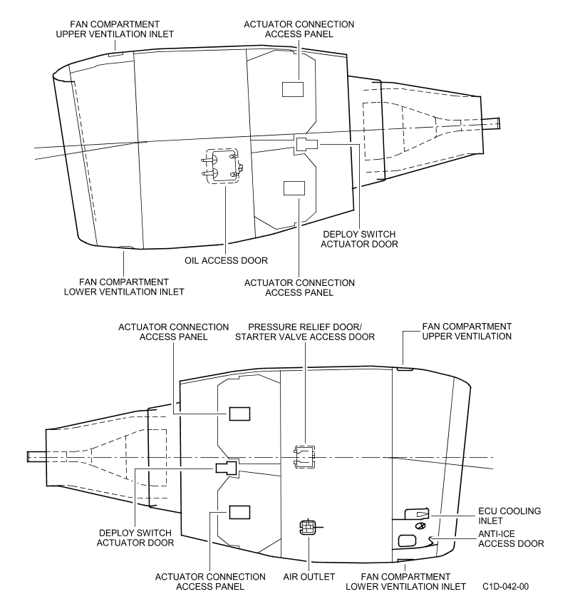
There are a total of five access and inspection locations in the air intake cowl. Three inspection panels are located on the aft bulkhead. (Ref. Fig. Access Panels on Air Intake Cowl SHEET 1) The access panel is located on the outer barrel and contains the anti-ice exhaust exit and pressure relief door. The fifth access location is on the forward bulkhead. This panel provides access to the anti-ice supply duct. The swirl nozzle is accessible after removing the dedicated anti-ice exhaust duct.
b. 风扇整流罩
The fan cowl door assemblies are interchangeable units. They enclose the engine fan case between the air intake cowl and thrust reverser. Each fan cowl door assembly incorporates strakes. Each assembly is supported by three hinges at the pylon and latched along the bottom centerline with three adjustable tension hook latches.
或者
The fan cowl door assemblies are interchangeable units. They enclose the engine fan case between the air intake cowl and thrust reverser. Inboard fan cowl door of each nacelle incorporates strakes. Each assembly is supported by three hinges at the pylon and latched along the bottom centerline with three adjustable tension hook latches
The fan cowls are bonded graphite epoxy skins and aluminum honeycomb sandwich construction. A land is effected with the air intake cowl at the forward end, and with the fan thrust reverser at the aft end. Both lands incorporate an edge protector. The forward land incorporates two fan cowl locator fittings (associated with air intake cowl alignment fitting). A composite outer skin of the fan cowl incorporates a lightning protection system consisting of an expanded copper screen (ECS) material. This material enables the fan cowl to satisfy Zone 1A lightning strike requirements. A bulb-type seal is provided along the lower longitudinal splitline and a sheet metal rub strip is provided along the upper longitudinal splitline which interfaces with a pylon mounted sheet metal seal. Strakes are installed on the right and the left side of the fan cowl doors of each engine. An electrical bonding strip, which is connected to the strake backplate and the fan cowl locator blade provides an electrical bond between the strake and the engine.
或者
The fan cowls are bonded graphite epoxy skins and aluminum honeycomb sandwich construction. A land is effected with the air intake cowl at the forward end, and with the fan thrust reverser at the aft end. Both lands incorporate an edge protector. The forward land incorporates two fan cowl locator fittings (associated with air intake cowl alignment fitting). A composite outer skin of the fan cowl incorporates a lightning protection system consisting of an expanded copper screen (ECS) material. This material enables the fan cowl to satisfy Zone 1A lightning strike requirements. A bulb-type seal is provided along the lower longitudinal splitline and a sheet metal rub strip is provided along the upper longitudinal splitline which interfaces with a pylon mounted sheet metal seal. Strakes are installed on the inboard fan cowl door of each engine. An electrical bonding strip, which is connected to the strake backplate and the fan cowl locator blade provides an electrical bond between the strake and the engine
Opening/Closing (Ref. Fig. Fan Cowl Door Opening SHEET 1) (Ref. Fig. Fan Cowl Door Hold Open Rods SHEET 1) There are two telescopic hold open rods on each door. The hold open rods lock to brackets on the engine fan case. They support the fan cowl doors in the open position. A 40-degree position serves for routine maintenance and a 55-degree position serves for increased access. Three hook type latches are provided on the left hand door, and mating adjusta-keeper clevis on the right hand door. The bottom seal pressure between the doors is adjustable by varying the shim pack thickness behind the latch striker pads. The latch handle closing pressure is adjustable with the fan cowl doors closed. 4. Access Doors/Pressure Relief Door (Ref. Fig. Fan Cowl Doors SHEET 1) (Ref. Fig. Fan Cowl Pressure Relief/Starter Access Door SHEET 1) (Ref. Fig. Oil Tank Access Door SHEET 1) A combination access/pressure relief door is provided in the right-hand fan cowl door for access to the starter valve manual override. This door also acts as a pressure relief door to protect the door structure in the event of a burst duct. The left-hand fan cowl door includes an access door for engine oil servicing and inspection of the hydraulic case drain filter clogging indicator and master oil chip detector indicator. The air outlet vent is located in the right-hand cowl panel lower aft section. The fan cowl doors are fireproof without external air flow above the 45-degree radial and fireproof with external air flow below the 45-degree radial. In addition, the doors are fire resistant without external air flow below the 45-degree radial. 5. Fan Cowl Structure The internal pressure loads and external air loads are reacted through the honeycomb structure. They are transmitted into the pylon through the hinge fittings. The door lands provide support to prevent deflection under pressure. The cowl doors, when completely latched, provide hoop continuity. The cowl doors are designed to be structurally adequate when any one latch is unlatched or any one hinge failed. A nacelle overpressurization condition due to a pneumatic duct failure is released through the pressure relief door. The pressure relief doors are designed to prevent fan compartment pressure from exceeding 4 psid (0.28 bar).
c. 反推整流罩和主排管
反推整流罩和主排管在78-00详解
3、吊架安装座
发动机通过前后两个容损安装座挂在吊架上。安装座是重要的安装结构,前安装座包括4个安装螺栓,将发动机直接连在吊架上,后安装座由连杆和横梁组成。
The engine/pylon connection is achieved by means of a two-mount system : · The forward mount is a damage-tolerant design consisting of a two-piece beam, single piece cross beam, and two links which attach to the pylon and aft fan case. Attached to the beam are two links which are attached to the engine attach brackets. These brackets attach to the engine fan case. · The aft mount is a damage-tolerant design consisting of a two-piece cross beam, that attaches to the pylon. From this beam, there are three, three-piece links which attach to the engine rear frame . 2. System Description (Ref. Fig. Engine Mount Loads SHEET 1) The engine mounts are designed for side, vertical, thrust and torque loads. The damage-tolerant assemblies consist of links and beams with swaged-in spherical bearings on the ends. The link and beam assemblies are bolted to the engine at the engine fan case and turbine rear frame mount, and interface with the pylon. Additional locking and retaining features are provided on the bolts, or pins, at structural attachment points. The engine mount design provides dual load paths to ensure safe operation should one member fail.
a. 前座
The forward mount connects the engine aft fan case with the engine pylon forward structure. The forward mount is a damage tolerant design. It consists of : · the support beam assembly : for pylon connection via 4 tension bolts and 2 alignment pins. This fail-safe designed fitting is an assembly of 3 components : 2 half-fittings and 1 plate. · one bearing fitted on the support beam assembly which carries y and z loads. The outer cage is axially free in the engine aft fan frame aperture and therefore carries no x loads. In case of lateral link failure, the bearing partially carries the x loads. · one link/beam/bracket assembly which carries the x thrust loads. The beam is hinged to the main bracket at its center. A link is installed at each end of the beam. A bracket attached to the engine casing supports the front of the link. The link ends have bearings.
b. 后座
The aft mount connects the engine turbine rear frame with the engine pylon via a beam. The aft mount takes the loads in the plane normal to the engine centerline, i.e. y, z loads and Mx. The aft mount is a damage tolerant design. It consists of 3 links and a crossbeam assembly. There is a possibility of axial translation movement between the engine casing and the pylon since : · the three links are located in the same plane normal to the engine centerline · the link end have bearings. There is a possibility of axial translation movement between the engine casing and the pylon. This allows for casing expansions of about 0.236 in. (6 mm) in cruise and 0.295 in. (7.5 mm) at maximum thrust. The lugs are located on the upper part of the turbine rear frame. Their angular position is plus or minus 56.25 degrees for the lateral lugs and 11.25 degrees for the upper lug. The aft mount consists of : · 3 fail-safe links. Each link is a triple element stacked assembly. These elements are connected by two attachments. The lower attachment of each link has a bearing. It provides attachment to the engine casing lugs : · a cross beam fitting. The cross beam has 3 lugs for attachment of the 3 links. Each lug includes a bearing. The cross beam has a mating face for connection with the engine pylon. This attachment is made through 4 tension bolts and 2 shear pins. One of the two shear pins is a back-up pin also used as an alignment pin. The cross beam fitting is a fail-safe design : it consists of two lateral parts linked by shear pins.
4、附件接头
附件接头和支架用于安装发动机附件:
- 发动机部件
- 各种管道
- 各种管子
- 各种电缆
附件接头和支架安装在:
- 发动机核心机
- 风扇机匣
- 附件
- 附件齿轮箱
5、电气线缆
电气线束有两大功能:
- 电能分配(电力电子)
- 信号传递(信息电子):
- 短舱子系统
- 发动机控制
- 监控功能
a. 风扇线缆
The electrical cables and harness on the fan case interface with the fan electrical junction box. The fan harnesses provide electrical power to the control and electrical monitoring systems located on the fan case and the accessory gearbox. (1) Electrical harness The electrical harness supplies power to, or transmits power from : · the fuel system : filter clogging indication · the oil system : oil quantity, low oil pressure, oil filter clogging, oil temperature, oil pressure · N1 system · N2 system · N1 bearing accelerometer · the hydraulic pumps system : by-pass valve, low pressure caution · the fan compartment fire detection system · the HP fuel shut off valve solenoid · the air intake anti ice system : anti ice valve position indicating · the IDG control and indicating (Ref. AMM D/O 24-00-00-00) · the ignition exciter · the interphone jack (which is located at the engine air intake) · Master chip detector indicator (2) ECU Control Harnesses (Ref. AMM D/O 73-00-00-00) . (3) IDG feeders The IDG transmits the electrical power to the systems via the feeders.
b. 核心机线缆
The electrical harness in the core area interfaces with the junction box. The core harness provides electrical power to the control and monitoring systems located in the core compartment : · core compartment fire detection system · pressure regulating valve and high pressure valve position indication (open and closed) · second vibration accelerometer.
C. Attachment and Connection (Ref. Fig. Harness - LH Side of Engine SHEET 1) (Ref. Fig. Harness - RH Side of Engine SHEET 1) (Ref. Fig. Fan Case Harness Connections to Pylon Junction Box SHEET 1) (Ref. Fig. Core Harness Connections to Pylon Junction Box SHEET 1) The harnesses and cables are routed around the engine. They are attached to the engine brackets by means of clips and clamps. The harness connectors are connected at the junction boxes which are located under the engine pylon. D. Harness Design (Ref. Fig. Harness Construction SHEET 1) All harnesses are of sealed construction and have double shielding (overbraid and shielded wire). Fire detector harnesses in the core area are not fully sealed. Basic EMI/Lightning protection are achieved with the outer overbraid and inner shields. The core harnesses use an outer sleeve protection system of either VITON or PEEK. The fan harnesses use an an outer sleeve protection system of either DR-25 or PEEK. On braid-shielded harnesses, a dedicated mechanical protection between the braid and the top coat of wires is provided such that penetration of the shielding in wire top coat is not possible.
6、排放
该系统用于给发动机附件和部件排放通风,将污液和蒸汽排出机外。
The drain and vent system consists of lines collecting and carrying waste fluids and vapor overboard from the engine and nacelle accessories. Drains are provided to carry fluids from any point where lines and accessories may leak and where fluids may accumulate in a cavity. In addition, some drain lines serve as vents to carry air and vapor from the engine and accessory cavities.
(Ref. Fig. Drain and Vent Schematic SHEET 1) (Ref. Fig. Drain System SHEET 1) The drain and vent system is divided into two parts; one which retains drained fluids until expelled during flight (reservoir), and one which discharges fluid directly overboard through the drain mast located in the fan compartment. The reservoir module is mounted on the transfer gearbox. The manifold module is also attached to the transfer gearbox and supports the drain mast, which protrudes through the fan cowl doors into the airstream. Each accessory pad seal has a separate drain cavity in the reservoir module in which leakage is contained. Manual drain valves in the bottom of these reservoirs aid in tracing the source of excess leakage. Each reservoir is identified with the accessory seal drain to which it is connected. These individual reservoirs overflow into the fuel holding tank or an hydraulic fluid/oil holding tank. This overflow is contained in the holding tank until the aircraft reaches an airspeed of 200 Knots. A pressure valve, which is part of the manifold module assembly, then admits ram air to pressurize the holding tanks and discharge any accumulated fluid overboard through the drain mast. The fluids that are discharged directly overboard are from: · the oil tank scupper · the forward sump · the fan case · the oil/fuel heat exchanger · the VBV · the VSV · the TCC · the aft sump · the fuel shroud pipe. For the shroud pipe no leakage is permissible, a separate drain line enables a clear leakage identification. · the 6 o'clock fire bulkhead. · FRV Based on two hour total flight profile (start, taxi, takeoff, cruise, descent, taxi), the individual reservoir volumes are twice the accumulated liquid level based on acceptable leakage rates. The volumes provide sufficient containment margin to discriminate between excessive and acceptable leakage rates. Fuel, Oil or hydraulic leakage limits are given in 71-00-00 P.Block 501.
Component Location (Ref. Fig. Drain System SHEET 1) (Ref. Fig. General Location SHEET 1) A. Drain Collector Assembly The drain collector assembly is attached to the aft side of the engine gearbox. B. Drain Module The drain module is attached directly to the aft side of the engine gearbox. It supports the drain mast. C. Drain Mast The drain mast is frangible below the cowl exterior surface to prevent damage to the engine gearbox. Should the drain mast strike the ground (or any object), the portion of the mast below the the cowling will break away. 4. Component Description A. Drain Collector Assembly (Ref. Fig. Collector Assembly SHEET 1) The drain collector assembly is composed of 4 drain collectors with manual drain valves and 2 holding tanks. The collector retains fluids until it is filled. Then the fluids overflow onto the holding tanks. B. Drain Module (Ref. Fig. Drain Mast SHEET 1) (Ref. Fig. Drain Module SHEET 1) It supports the drain mast which protrudes through the fan cowl doors into the airstream. A pressure valve which is a part of the drain module, admits ram air at 200 Knots. It pressurizes the holding tanks and enables discharge of any accumulated fluid overboard through the drain mast.